“Constructing a charger showing phenomenon of transmission line”
“Constructing a charger showing phenomenon of transmission line”
1
Objective:
The objective of this experiment is to study
the characteristics of transmission line using a charger.
2
Abstract:
With
the ever increasing role of communications in our daily lives, it has become
important
to
connect remote sites together to share data and information. One method for
providing
links
between remote sites is to use transmission lines. Transmission lines are classified as short, medium and long. In
this experiment a mobile charger is made to show the phenomenon of transmission
lines using some important components diodes, capacitors, transformer, Vero
board etc.
3
Introduction:
3.1
Transmission Lines:
A conductor or conductors designed to carry electricity or an electrical
signal over large distances with minimum losses and distortion. A system of structures,
wires, insulators and associated hardware that carry electric energy from one
point to another in an electric power system. The material medium or
structure that forms all or part of a path from
one place to another for directing the transmission of
energy, such as electric currents, magnetic fields, acoustic waves, or
electromagnetic waves.
3.2
Classification of transmission lines
Transmission lines are classified as short, medium and long. When the
length of the line is less than
about 80Km the effect of shunt
capacitance and conductance is neglected and the line is designated as a short transmission line. For these lines the operating voltage is less than 20KV.
For medium transmission lines the length of the line is in between 80km - 240km and the operating line voltage will be in between 21KV-100KV.In this case the shunt capacitance can be assumed to be lumped at the middle of the line or half of the shunt capacitance may be considered to be lumped each end of the line.
For medium transmission lines the length of the line is in between 80km - 240km and the operating line voltage will be in between 21KV-100KV.In this case the shunt capacitance can be assumed to be lumped at the middle of the line or half of the shunt capacitance may be considered to be lumped each end of the line.
Lines more
than 240Km long and line voltage above 100KV require calculations in terms of
distributed parameters. Such lines are known as long transmission lines. This
classification on the basis of length is more or less arbitrary and the real
criterion is the degree of accuracy required.
3.3
Step Down Transformer:
Step down transformers are designed to reduce electrical
voltage. Their primary voltage is greater than their secondary voltage. This
kind of transformer "steps down" the voltage applied to it.
3.4
Rectification:
Rectification is the conversion of alternating current
(AC) to direct current (DC). A half-wave rectifier is a circuit that allows
only one half-cycle of the AC voltage waveform to be applied to the load,
resulting in one non-alternating polarity across it. A full wave rectifier is a
circuit that allows full of the wave to be rectified.
3.5
Capacitor:
Capacitor is a device specifically designed to
hold an electrical charge. The number of electrons a capacitor can hold
for a given voltage is a measure of its capacitance. In its basic form, a Capacitor consists of two or more parallel
conductive (metal) plates which are not connected or touching each other, but
are electrically separated either by air or by some form of a good insulating
material such as waxed paper, mica, ceramic, plastic or some form of a liquid
gel as used in electrolytic capacitors. Capacitors
are used as filter in rectification or to remove the fluctuation in DC voltage.
3.6
Diode:
A diode is an electrical device allowing
current to move through it in one direction with far greater ease than in the
other. The most common kind of diode in modern circuit design is the semiconductor diode, although other diode
technologies exist.
Current
is flown only when diode is forward biased, in reverse biased current is
prohibited.
4
Principle:
Charger is operated on the
principle of stepping down the voltage with the help of step down transformer
5
Apparatus:
i.
Vero
Board
ii.
Power
Supply (220V)
iii.
4
Diodes
iv.
12
V Step down Transformer
v.
Variable
Resistor (0-12V)
6
Circuit:
7
Experimentation:
I.
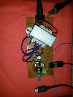
I made all the connections as shown in diagram.
II.
Then I gave AC input of 220V to a Centre tapped transformer which
provides only 12V, the voltage is made step down.
III.
After the signal was rectified, I have inserted capacitors so that we
don’t get pulses. They act as filters.
IV.
Then a variable resistor is connected through which we can vary the
value of voltage from 0-12 volts.
V.
I obtained the DC output by connecting a data cable in the female USB
port.
VI.
Then I observed the output in the form of charging of mobile.
VII.
The LEDs connected in the circuit just show that there is current
flowing through the circuit.
Sr.
No.
|
Voltage
( V)
V
|
Resistance
(R)
ohm
|
Current
(I)
A
|
P=VI
watts
|
P=
watts
|
1
|
2.91
|
327
|
8.5
mA
|
0.024
|
0.0236
|
2.
|
3.27
|
10
|
327
|
1.069
|
1.069
|
3.
|
2.94
|
460
|
5.97mA
|
0.017
|
0.016
|
8.
Observations and calculations
Using different
resistances in the circuit:
9.
Results & Discussion:
In this experiment Alternating current is
converted into direct current to charge the battery of required voltage. Any
cell phone is charged using the resulted DC battery. If the voltage is
increased to the value of voltage that is required then the mobile gets readily
charged and the excess amount of voltage drops across resistor. Capacitor is
used as to smooth the DC curve obtained by rectification. power is calculated
by varying the value of resistor using variable resistor.


Comments
Post a Comment